Integrated Smoke Alarm Delta Mod

This is an implementation of using a photoelectric smoke detector to trigger the reset pin on the Beaglebone Black Rev C being used on the MOST Athena Delta 3D Printer. The purpose of this design is to prevent and minimize printer damage, overheating, temperature runoff, and fire risk when a 3D printer is running unattended.
Materials & Tools Needed
- Photoelectric Smoke Alarm of any kind, such as the one (not the model pictured in this tutorial) -- SCAD models made for one with a 12" mounting disk, but can be modified for other types
- 5 M3 Screws of 15 mm length
- 5 M3 nuts
- 18 Gauge wire - roughly 3.5 - 4 feet total
- 9 Volt Battery
- Soldering Iron
- Flathead Screwdriver
- Superglue
Items to 3D Print
- Smoke Alarm mount Arms -- Smoke Alarm Mount Arms
- Smoke Alarm Mount Disk -- Smoke Alarm Mount Disk
Instructions
- Print off 3 Arms and one Base Fixture; set models to a scale of 10 in your slicer.
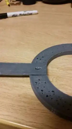 Fig.1: Close up of fixture and joint connected
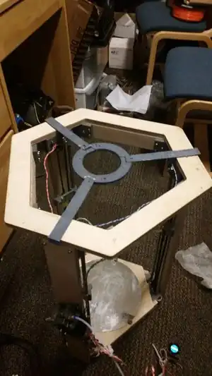 Fig.2:View of mod frame from top
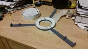 Fig.3:Mount with Bracket
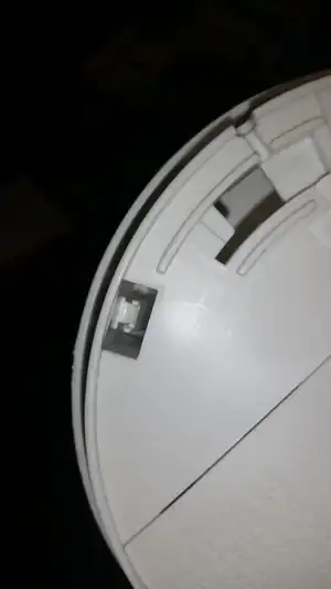 Fig.4:Pins to be opened to access electronics of smoke detector
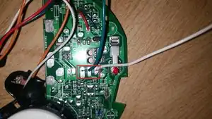 Fig.5:Smoke Alarm electronics with Sound output pins highlighted
- Place 9 Volt Battery into smoke alarm.
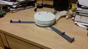 Fig.6:Mount with Detector
- Place assembly onto printer frame.
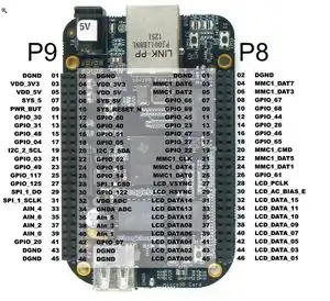 Fig.7:Beaglebone Pinout, from beaglebone/blog/2014/11/26/controlling-the-beaglebone-blacks-gpio-pins-from-the-internet-1 Element14
Notes, Known issues and possible fixes
current Design causes the fire alarm to constantly trigger reset of the Beaglebone when smoke is detected, preventing the Beaglebone from turning on until the fire alarm is reset.
Future Improvements
A future improvement is to set the output of the smoke alarm to a data pin on the beaglebone, scripted to stop Firmware (i.e. Franklin) and send an email / notification to the printer owner, then shutting off the entire system.
This article is issued from Appropedia. The text is licensed under Creative Commons - Attribution - Sharealike. Additional terms may apply for the media files.