WetLand water meter instructions
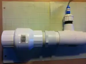
A section of the sampling compartment with the pH sensor integrated
The steps laid out below are for the Water Meter designed by Team X for the WetLand Barge
This page is designed to be used injunction with the Water Meter's main Appropedia page WetLand water meter
Building the Circuit
Materials
- Arduino
- Sensor shield
- Data logger
- SD card
- 22 gauge wire (3-4 colors for clarity)
- soldering wire
- Sensors
- pH
- electrical conductivity
- temperature
- volume
- flow rate (2)
Tools
- Soldering Gun
- Wire strippers
Step by Step
| Step Number | Instruction |
|---|---|
| 1 | Download Arduino programming software onto computer via http://arduino.cc/. |
| 2 | Plug Arduino into computer via USB cable. |
| 3 | Upload various sensor codes into separate tabs on the Arduino. Code for each sensor can be found here; https://www.appropedia.org/Team_X_Water_Meter_Arduino_Code |
| 4 | Plug Sensor Shield into the Arduino aligning all pins. |
| 5 | Plug Data storage shield into the sensor shield aligning all pins. |
| 6 | Solder Temperature sensor wires to 3 prong male header. |
| 7 | Solder Sonar sensor to 4 prong female header using 4-5 foot strips of 22 gauge wire. |
| 8 | Extend the Flow rate gauge wire length by cutting its wiring and soldering a 5ft piece of 22 gauge wire into the middle section. |
| 9 | Plug Temperature sensor, Sonar sensor, Electrical Conductivity sensor, and Flow Rate Gauge into sensor shield and adjust analog input in Arduino code values accordingly. |
| 10 | Plug Ph sensor probe into Arduino following the wiring diagram shown here; http://web.archive.org/web/20150905225735/http://atlas-scientific.com:80/_files/instructions/Wiringdiagram.pdf |
| 11 | Solder Arduino to LCD screen using 10ft 22 gauge wire. Wiring diagram for 16 pin LCD (shown right) can be found here; http://web.archive.org/web/20150906074008/https://www.arduino.cc/en/Tutorial/LiquidCrystal |
| 12 | Plug SD card into data storage shield. |
Building the Sampling Compartment
Materials
- One 1 foot. of 2 inch PVC pipe
- One 2 inch PVC T-pipe 2 inch top
- one 2 inch PVC T-pipe 1 inch top
- One 2 inch PVC cap
- One 1 inch PVC cap
- One 2 inch PVC threading
- Two cans of PVC primer
- Two cans of PVC cement
- One 2 inch PVC flow regulator
- One 2 inch PVC male adapter
Tools
Drill
Saw
| Step Number | Instruction |
|---|---|
| 1 | Cut with a saw 1 foot of 2 inch in diameter PVC pipe into 3 sections |
| 2 | Drill.5 inch hole in 1 inch PVC cap for the pH sensor |
| 3 | Drill.25 inch hole in 2 inch PVC cap for the temperature sensor |
| 4 | Cut 1 inch slit in 2 inch cap that has the.25 inch hole already for the saline sensor |
| 5 | Drill.25 inch hole in second 1 inch cap for the flow rate sensor |
| 6 | Apply PVC primer to 2 inch PVC male adapter's threading |
| 7 | Apply PVC cement to 2 inch PVC male adapter's threading |
| 8 | Connect 2 inch PVC male adapter to 2 inch PVC flow regulator's flow out threading |
| 9 | Apply PVC Primer to the outside of the ends of the 2 inch 3 sections PVC pipe |
| 10 | Apply PVC Primer to the inside of the ends of the t-pipes and male adapter |
| 11 | Apply PVC cement to the outside of the ends of the 2 inch 3 sections PVC pipe. |
| 12 | Connect 1 section of 2 inch PVC pipe to male adapter. |
| 13 | Connect the 2 inch PVC T-pipe with the 1 inch top into the 2 inch PVC pipe section from step #11 |
| 14 | Connect the middle section of the 2 inch PVC pipe to the 2 inch PVC T-pipe with a 1 In top |
| 15 | Connect the 2 inch PVC T-pipe with 2 inch top into the 2 inch PVC pipe section from step #13 |
| 16 | Connect the remaining section of 2 inch PVC pipe to the 2 inch PVC T-pipe with 2 inch top |
| 17 | Apply primer to the inside of the tops of the PVC t-pipe |
| 18 | Apply primer to half of each of the threading section(this will spread when the cap is screwed on) |
| 19 | Apply cement to the same half on each of the threading section |
| 20 | Insert the threading sections into the tops of PVC t-pipes and leave about 2 inches showing |
| 21 | Screw PVC caps to PVC t-pipe threading sections that are showing |
Installation of the Sampling Compartment
| Step Number | Instruction |
|---|---|
| 1 | Insert into plumbing after water tank but before faucet |
| 2 | If needed use an adapter to scale up to the 2 inch sampling compartment |
| 3 | Connect Sampling compartment to existing plumbing in easily accessible and secure location |
| 4 | Apply PVC primer and cement to ends of Sampling compartment |
| 5 | Apply PVC primer to ends of plumbing that are going to be connected to sampling compartment |
| 6 | Screw sampling compartment on to existing plumbing |
Installing the Electronics
| Component | Step Number | Instruction |
|---|---|---|
| Sonar Sensor | 1 | Drill two holes in piece of plywood that is 1 foot by 1 foot in square area |
| 2 | Fasten sensor to plywood with the sonar emitters fitting into the holes | |
| 3 | water proof the sensor by covering the sonar emitters with silicone | |
| 4 | Place the sensor over the IBC tote in a position that the sonar emitters have a clear path to the water, such as over the lid | |
| pH Sensor | 1 | Sensor is water proof |
| 2 | Sensor is integrated into the sampling compartment | |
| 3 | Insert the sensor such that the cable coming out and going away from the sensor and the PVC pipe | |
| Electrical Conductivity Sensor | 1 | The sensor must first be water proofed above the actual sensing strip, which is the black metal section with vertical lines on it, with silicone resin |
| 2 | Sensor is integrated into the sampling compartment | |
| 3 | Insert the sensor such that the cable coming out and going away from the sensor and the PVC pipe | |
| Temperature Sensor | 1 | Sensor is water proof |
| 2 | Sensor is integrated into the sampling compartment | |
| 3 | Insert the sensor such that the cable coming out and going away from the sensor and the PVC pipe | |
| Flow Rate Sensors | 1 | These sensor are water proof |
| 2 | One meter is set at the inlet of the storage tank | |
| 3 | Connect by scaling down the piping if necessary, the sensor has a 0.5 inch diameter | |
| 4 | Screw the sensor into the piping | |
| 5 | Second meter is set at the outlet of the storage tank | |
| 6 | Connect the second flow rate sensor by applying PVC primer and cement to the threads of the flow sensor | |
| 7 | Screw sensor into the on board.5 inch water pump | |
| Sensor Shield | 1 | Place on top of the Arduino |
| 2 | Plug the sensors into the corresponding sensor pins | |
| Data Storage Shield and SD Card | 1 | Place on top of the Sensor shield |
| 2 | Insert the SD Card into the slot on the Data Storage shield | |
| LCD Screen | 1 | Make a metal box to fit the screen in with one side open to be the front where the screen will display |
| 2 | Cut a 1 inch diameter hole in the back for the wires to fit through | |
| 3 | Obtain a car GPS mount to attach the box to | |
| 4 | Using a 0.5 diameter metal rod attach a 1 foot by 1 foot square area piece of sheet metal to the base of the rod to be the stand | |
| 5 | Attach the GPS mount to the top of the metal rod to complete the display mount |
This article is issued from Appropedia. The text is licensed under Creative Commons - Attribution - Sharealike. Additional terms may apply for the media files.