SCRAP Humboldt community tinker desk instructions
Building the Community Tinker Desk
Here you will find a list of diagrams that will assist you in recreating the Community Tinker Desk by 'The Planeteers'.
Table Cut Sheet
| Part# | Material | Length (in.) | Width (in.) | Height (in.) | Quantity |
|---|---|---|---|---|---|
| TOP | Door | 79 1/4 | 30 1/4 | 1 3/4 | 1 |
| EP1 | Door | 29 3/4 | 24 1/4 | 1 3/4 | 2 |
| CBL | Door | 55 1/4 | 16 | 1 3/4 | 1 |
| T30 | Post | 29 1/4 | 1 3/4 | 5/8 | 4 |
| TC | Post | 11 1/2 | 1 3/4 | 5/8 | 2 |
| TA1[1] | Post | 30 1/4 | 1 3/4 | 5/8 | 2 |
| TA2[1] | Post | 79 1/4 | 1 3/4 | 5/8 | 2 |
| T55 | Post | 55 1/4 | 1 3/4 | 5/8 | 1 |
| Part# | Description | Quantity |
|---|---|---|
| R12B[2] | Lag-Bolts 1/2" x 12" | 4 |
| LBA[3] | L-Brackets | 8 |
| P | Floor Pads | 4 |
Assembly of Table
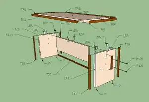
Diagram of the entire Community Tinker Desk in expanded format.
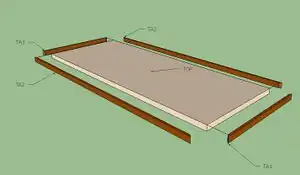
An overview of the table top. Glue and clamp/nail the parts TA1, TA2, and TOP together.
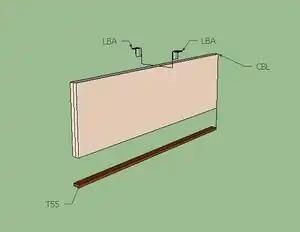
This is the shear brace for the table. Glue clamp/nail T55 to CBL and position LBA’s on the top side.
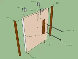
This is the table leg. Glue and nail/clamp T30 to EP1. Glue and nail TC to the center of EP1 and down 3 inches from the top side of EP1. Once TC is mounted, drill corresponding pilot holes for the lag-bolts R12B. Place either homemade or store bought protective pads (P) 2-3 inches in from the ends of EP1.
Bench Cut Sheet
| Part# | Material | Length (in.) | Width (in.) | Height (in.) | Quantity |
|---|---|---|---|---|---|
| BTOP | Door | 79 1/4 | 9 1/2 | 1 3/4 | 2 |
| BE[4] | Door | 16 1/2 | 14 3/4 | 1 3/4 | 4 |
| BBC | Door | 50 | 7 1/4 | 1 3/4 | 2 |
| TBA1[1] | Post | 9 1/2 | 1 3/4 | 5/8 | 4 |
| TBA2[1] | Post | 79 1/4 | 1 3/4 | 5/8 | 4 |
| TBCC | Post | 8 1/2 | 1 3/4 | 5/8 | 4 |
| TAL[4] | Post | 16 3/4 | 1 3/4 | 5/8 | 8 |
| Part# | Description | Quantity |
|---|---|---|
| R38B[2] | Lag-Bolts 3/8" x 12" | 8 |
| LBA[3] | L-Brackets | 12 |
| P | Floor Pads | 8 |
Assembly of Bench
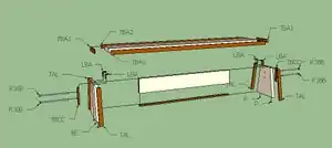
Diagram of one of the two identical benches in expanded format.
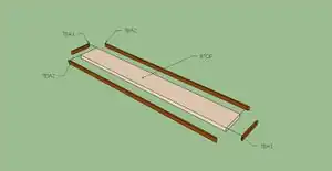
An overview of the Bench top. Glue and clamp/nail the parts TBA1, TBA2, and BTOP together.
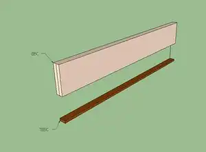
This is the shear brace for the Bench. Glue clamp/nail TBBC to BBC. Use two LBA’s as used on the table brace.
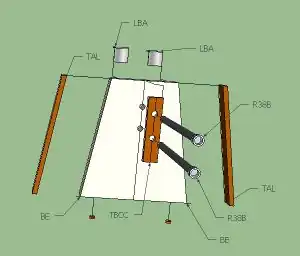
This is the bench leg. Glue and nail/clamp TAL to BE. Glue and nail TBCC to the center of BE. Use this diagram for referencing pilot holes for lag-bolts and angle cuts required for both BE and TAL parts. Once TBCC is mounted, drill corresponding pilot holes for the lag-bolts (R38B). Place either homemade or store bought protective pads (P) two inches inward from the ends of BE.
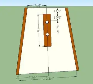
A side view of the bench leg. Notice the triangular shape. Special care should be taken to ensure the proper cutting of materials.
Notes
- 1 2 3 4 Needs 45ᵒ cut for special joining. These Parts require a miter joint in the corners.
- 1 2 Lag bolts require washers and pre-drilled holes for mounting.
- 1 2 Use L-Brackets with at least 1 ¼ inch wood screws. If door thicknesses vary for some reason, use mounting screws that penetrate at least one half the thickness of the wood.
- 1 2 Requires an 80ᵒ cut to prevent bench user from swaying back and forth.